4 Input 7 Segment Display Truth Table / Fpga Serial Ii Display Seven Segment Yg S Site
The output of driver integrated circuit is approximately equal to 25 ma of current to drive the led … The decoder takes these four bits and convert them to 7 bits to produce the desired decimal digit to display on the seven segment. The best example of decoder.

23.03.2022 · a decoder is a combinational logic circuit that has 'n' input signal lines and 2 n output lines.
The resistors will lower down the voltages but the value 220ohm is only for 5v output devices. The output of driver integrated circuit is approximately equal to 25 ma of current to drive the led … 2.4.5, a typical display consists of 7 leds arranged in a figure of 8 formation. The decoder takes these four bits and convert them to 7 bits to produce the desired decimal digit to display on the seven segment. The leds (labelled a to g) must be activated. In addition, we provide 'enable' to the input to ensure the decoder is functioning whenever enable is 1 and it is turned off when enable is 0. 23.03.2022 · a decoder is a combinational logic circuit that has 'n' input signal lines and 2 n output lines. In the 2:4 decoder, we have 2 input lines and 4 output lines. Decoding is essential in applications like data multiplexing, memory address decoding, and 7 segment display. The increase in voltage will lead to an increase in resistors. The diagram below shows the led segment patterns for each digit. The truth table, logic diagram, and.
The resistors will lower down the voltages but the value 220ohm is only for 5v output devices. For the display to work, these …

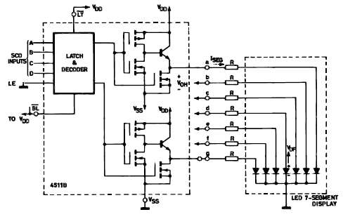
The four side input is named as a, b, c and d.
In the same way, other segments can also be made high. The increase in voltage will lead to an increase in resistors. For the display to work, these … The resistors will lower down the voltages but the value 220ohm is only for 5v output devices. In addition, we provide 'enable' to the input to ensure the decoder is functioning whenever enable is 1 and it is turned off when enable is 0. The output of driver integrated circuit is approximately equal to 25 ma of current to drive the led … Table 2.4.2 shows an example of a truth table for a bcd to 7 segment decoder, the purpose of this circuit is to illuminate the leds (or activate the lcd segments) that make up typical numerical displays. The truth table, logic diagram, and. Add the resistor of 220 ohms at each input pins. As we know that, seven segment devices display numbers according to control signal pattern and their respective led segments turn on and turn off pattern.
The decoder takes these four bits and convert them to 7 bits to produce the desired decimal digit to display on the seven segment. Table 2.4.2 shows an example of a truth table for a bcd to 7 segment decoder, the purpose of this circuit is to illuminate the leds (or activate the lcd segments) that make up typical numerical displays. Patent 1,126,641), when carl kinsley invented a method of telegraphically transmitting letters and numbers and having them printed on tape in a segmented format.in 1908, f. In the 2:4 decoder, we have 2 input lines and 4 output lines. In addition, we provide 'enable' to the input to ensure the decoder is functioning whenever enable is 1 and it is turned off when enable is 0. The resistors will lower down the voltages but the value 220ohm is only for 5v output devices.

The resistors will lower down the voltages but the value 220ohm is only for 5v output devices.
23.03.2022 · a decoder is a combinational logic circuit that has 'n' input signal lines and 2 n output lines. In addition, we provide 'enable' to the input to ensure the decoder is functioning whenever enable is 1 and it is turned off when enable is 0. The output of driver integrated circuit is approximately equal to 25 ma of current to drive the led … In the 2:4 decoder, we have 2 input lines and 4 output lines. The decoder takes these four bits and convert them to 7 bits to produce the desired decimal digit to display on the seven segment. The truth table, logic diagram, and. The leds (labelled a to g) must be activated. Table 2.4.2 shows an example of a truth table for a bcd to 7 segment decoder, the purpose of this circuit is to illuminate the leds (or activate the lcd segments) that make up typical numerical displays. Decoding is essential in applications like data multiplexing, memory address decoding, and 7 segment display. Patent 1,126,641), when carl kinsley invented a method of telegraphically transmitting letters and numbers and having them printed on tape in a segmented format.in 1908, f.
4 Input 7 Segment Display Truth Table / Fpga Serial Ii Display Seven Segment Yg S Site. Table 2.4.2 shows an example of a truth table for a bcd to 7 segment decoder, the purpose of this circuit is to illuminate the leds (or activate the lcd segments) that make up typical numerical displays. 2.4.5, a typical display consists of 7 leds arranged in a figure of 8 formation. Add the resistor of 220 ohms at each input pins.
The truth table, logic diagram, and 7 segment display truth table. The best example of decoder.

The resistors will lower down the voltages but the value 220ohm is only for 5v output devices. The four side input is named as a, b, c and d. 23.03.2022 · a decoder is a combinational logic circuit that has 'n' input signal lines and 2 n output lines. As we know that, seven segment devices display numbers according to control signal pattern and their respective led segments turn on and turn off pattern. 07.05.2020 · the bcd to seven segment display decoder or driver takes 4 inputs and produces 7 outputs. In addition, we provide 'enable' to the input to ensure the decoder is functioning whenever enable is 1 and it is turned off when enable is 0.

The truth table, logic diagram, and. In addition, we provide 'enable' to the input to ensure the decoder is functioning whenever enable is 1 and it is turned off when enable is 0. 2.4.5, a typical display consists of 7 leds arranged in a figure of 8 formation. The resistors will lower down the voltages but the value 220ohm is only for 5v output devices. The output of driver integrated circuit is approximately equal to 25 ma of current to drive the led …
Patent 1,126,641), when carl kinsley invented a method of telegraphically transmitting letters and numbers and having them printed on tape in a segmented format.in 1908, f. The increase in voltage will lead to an increase in resistors.

23.03.2022 · a decoder is a combinational logic circuit that has 'n' input signal lines and 2 n output lines. Decoding is essential in applications like data multiplexing, memory address decoding, and 7 segment display. Patent 1,126,641), when carl kinsley invented a method of telegraphically transmitting letters and numbers and having them printed on tape in a segmented format.in 1908, f. 2.4.5, a typical display consists of 7 leds arranged in a figure of 8 formation. In addition, we provide 'enable' to the input to ensure the decoder is functioning whenever enable is 1 and it is turned off when enable is 0.

Table 2.4.2 shows an example of a truth table for a bcd to 7 segment decoder, the purpose of this circuit is to illuminate the leds (or activate the lcd segments) that make up typical numerical displays. The diagram below shows the led segment patterns for each digit.
For the display to work, these … The resistors will lower down the voltages but the value 220ohm is only for 5v output devices. The output of driver integrated circuit is approximately equal to 25 ma of current to drive the led …

As we know that, seven segment devices display numbers according to control signal pattern and their respective led segments turn on and turn off pattern.

In addition, we provide 'enable' to the input to ensure the decoder is functioning whenever enable is 1 and it is turned off when enable is 0. The resistors will lower down the voltages but the value 220ohm is only for 5v output devices.

The leds (labelled a to g) must be activated.

The four side input is named as a, b, c and d.

07.05.2020 · the bcd to seven segment display decoder or driver takes 4 inputs and produces 7 outputs.

The decoder takes these four bits and convert them to 7 bits to produce the desired decimal digit to display on the seven segment.

2.4.5, a typical display consists of 7 leds arranged in a figure of 8 formation.

Post a Comment for "4 Input 7 Segment Display Truth Table / Fpga Serial Ii Display Seven Segment Yg S Site"